Engineering Projects
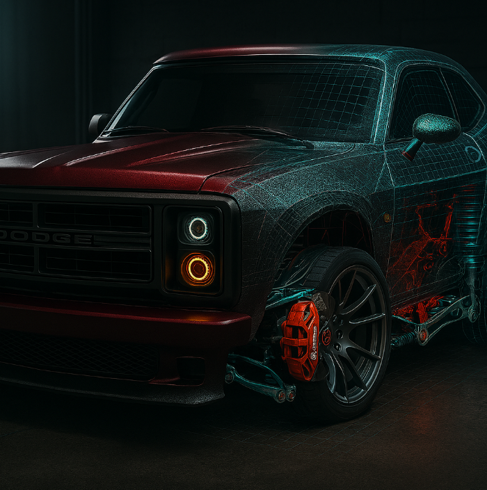
1984 Dodge D150 Modernization (392 HEMI + Challenger Subframes)
A ground-up engineering rebuild integrating modern OEM systems into a classic chassis. Work includes CAD-driven bracket design, structural fabrication, packaging and integration, and system-level planning across drivetrain, suspension, braking, HVAC, electrical, and exhaust (dual-mode valvetronic).
The project focuses on delivering modern performance, safety, and drivability within the constraints of a classic vehicle architecture.
ASME eHPVC: Human-Powered Vehicle Design & Fabrication
Design and fabrication of a competition human-powered vehicle with emphasis on mechanical design, suspension/steering kinematics, structural analysis, and manufacturability. Includes iterative CAD development, component testing, and integration for performance and reliability under competition constraints.
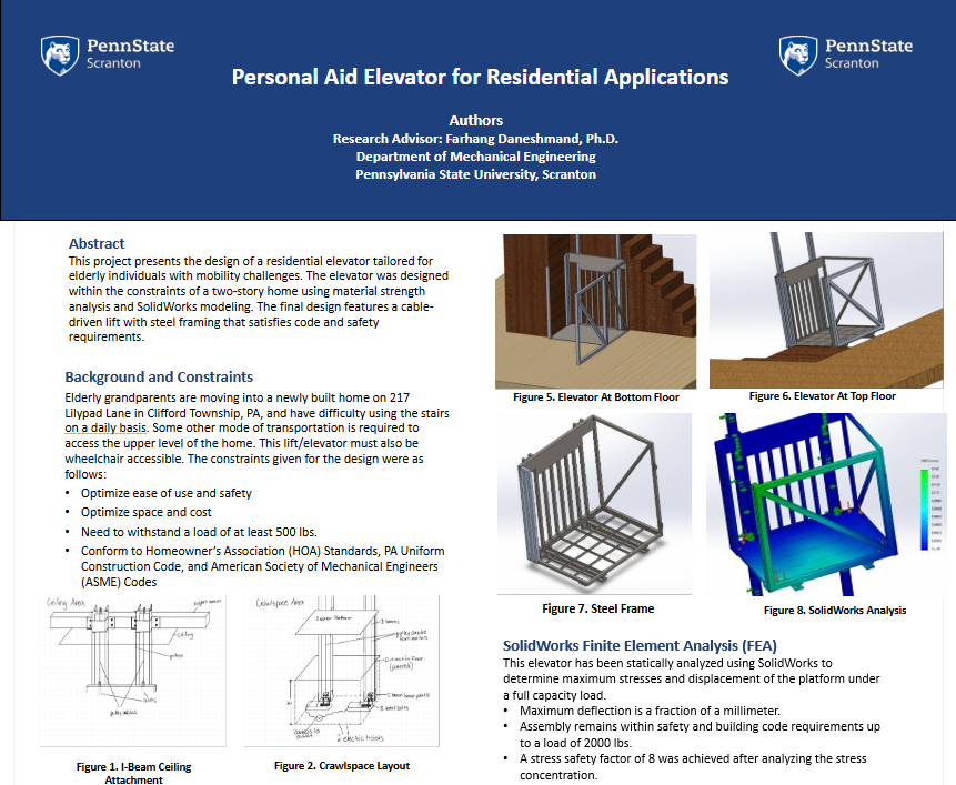
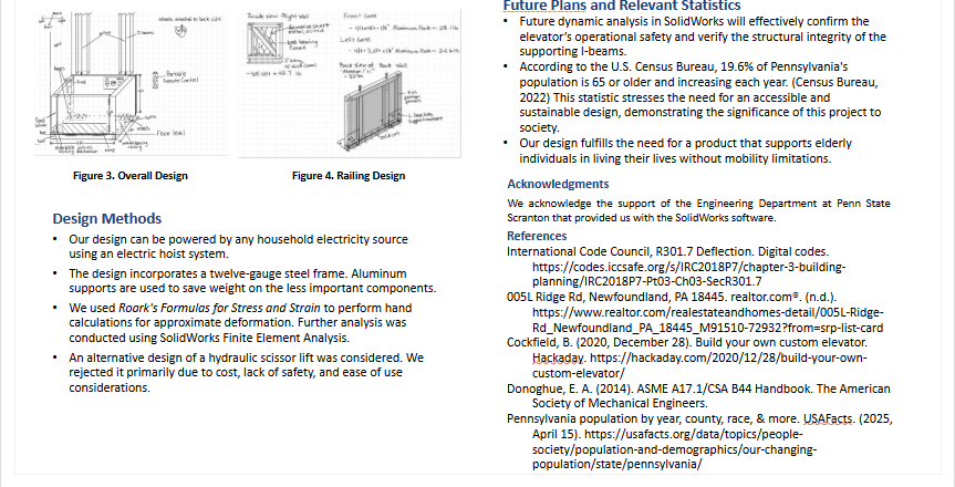
Residential Elevator System Design
Mechanical design and analysis of a residential elevator/lift system focused on accessibility, safety, code constraints, and defined load requirements. The project emphasizes conservative engineering assumptions and real-world applicability.
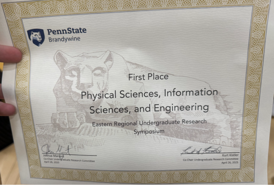
Awards: First Place – Penn State Scranton Undergraduate Research Fair; First Place – Penn State Eastern Regional Undergraduate Research Symposium (Brandywine)

Undergraduate Research: 3D Scanning Accuracy Validation
Research evaluating the dimensional accuracy and repeatability of a consumer-grade structured-light 3D scanner using baseline measurements, repeated trials, CAD comparison, and real-world validation through engineered fitment.
Awards:
ASME IMECE 2025 – Third Place (International Conference)
Penn State MC-REU 2025 – Researcher’s Choice Award
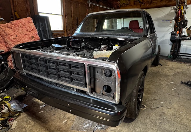
1984 Dodge D150 — Full Vehicle Systems Engineering Project
Project Overview
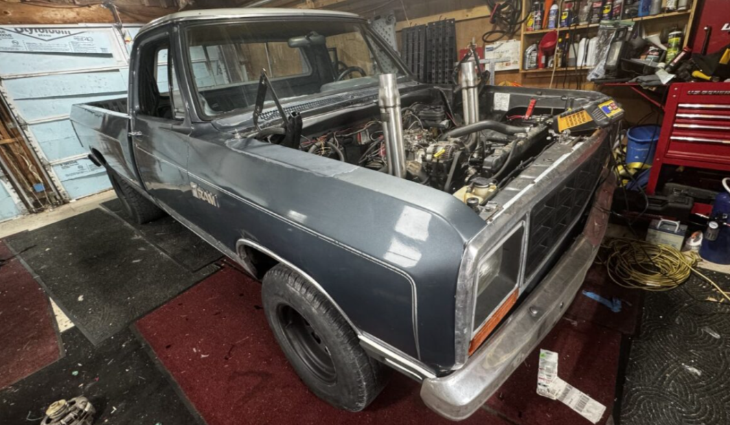
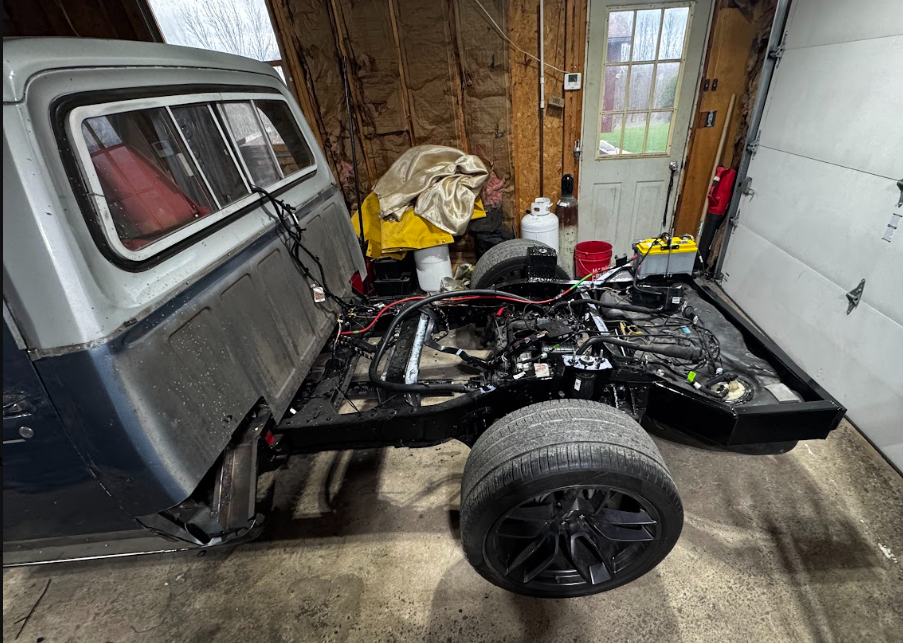
This project involves the full systems-level modernization of a 1984 Dodge D150 pickup using components from a 2022 Dodge Challenger Scat Pack Widebody. The scope includes powertrain integration, suspension and subframe geometry, structural reinforcement, electrical and electronic systems integration, and drivability optimization.
The objective is not cosmetic restoration, but the engineering development of a fully functional, modernized vehicle platform capable of OEM-level performance, reliability, and serviceability within the constraints of a legacy chassis.
This project integrates all important modern systems, including:
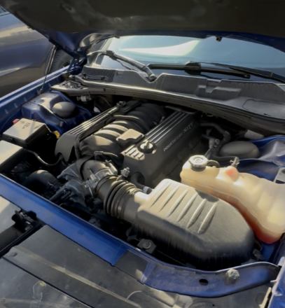
Modern Powertrain (6.4L hemi and TR6060 6 speed manual)
Independent suspension subframe systems in front and rear
Electronic Power Steering
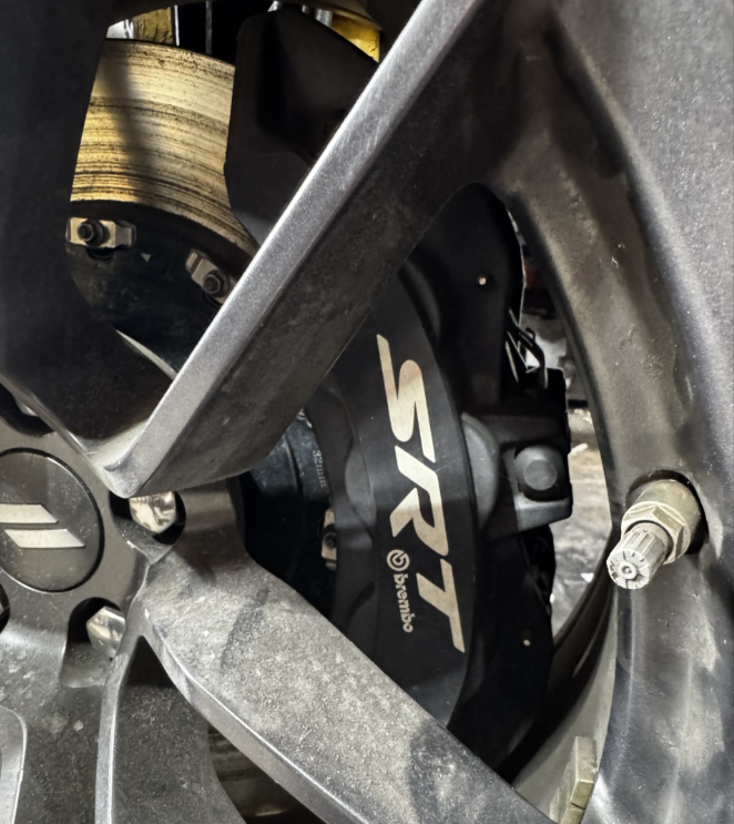
ABS-controlled 4 and 6-piston Brembo Brakes
Adaptive Damping Suspension
Modern 3.92 limited-slip rear differential
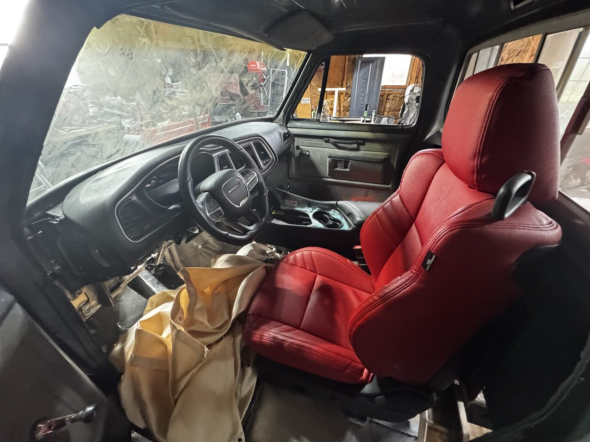
Modern HVAC w/ factory dash outlets and automatic controls
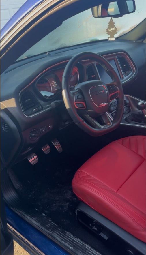
Power-adjustable heated leather seats
Full digital dash and modern CarPlay-compatible infotainment system
LED projector beam headlights
Valve-tronic controllable loudness exhaust system (Custom)
Electronic system modules: Power control module, Body control module, Airbag control module, etc.
1984 Dodge D150 Square body truck
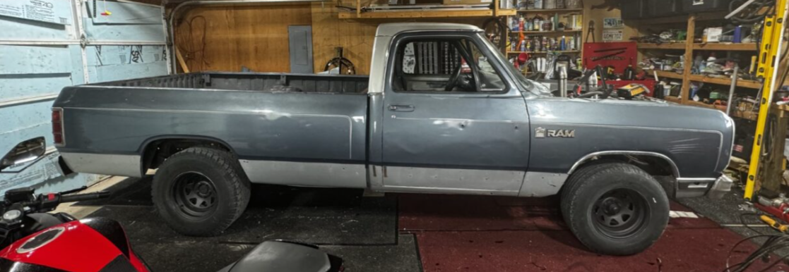
Project Vehicle
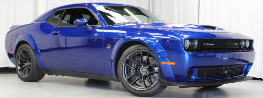
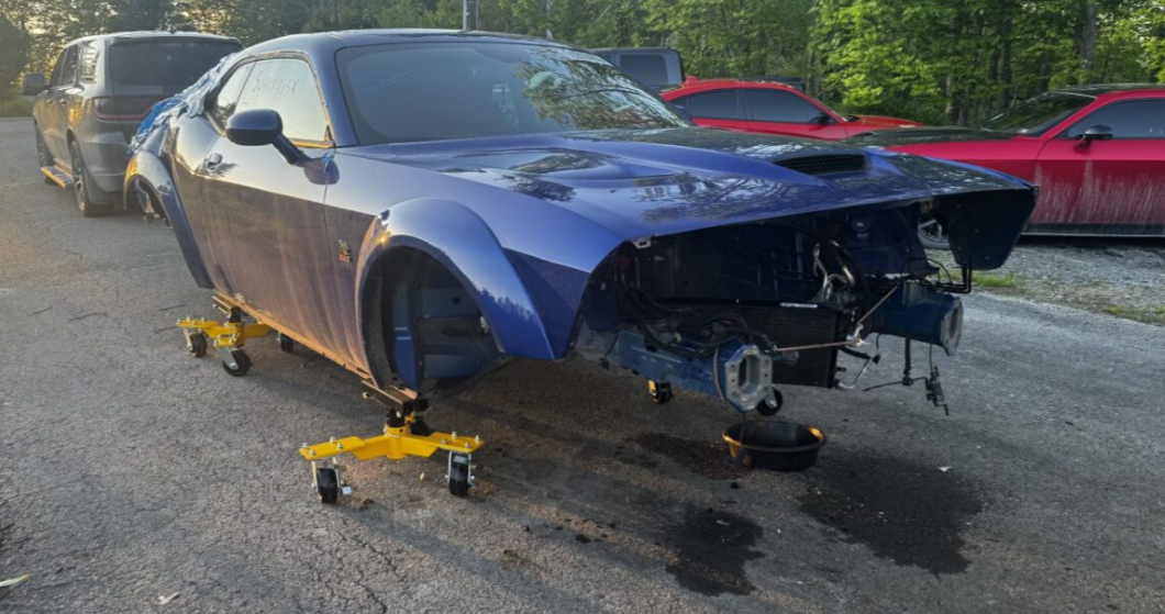
Donor Vehicle
2022 Dodge Challenger Scat Pack Widebody, w/6.4L and 6-speed manual
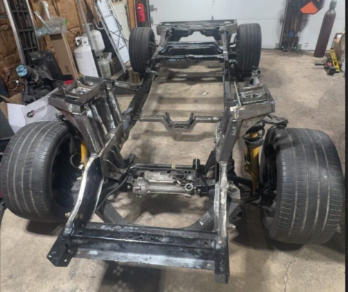
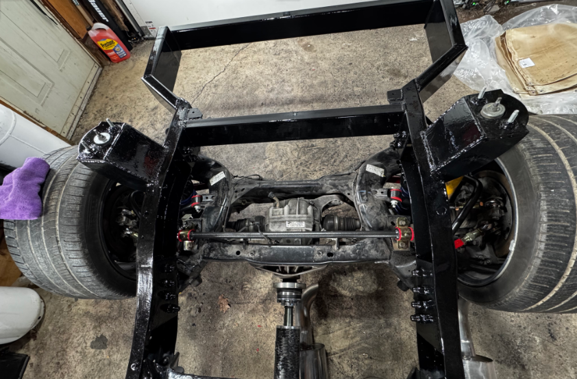
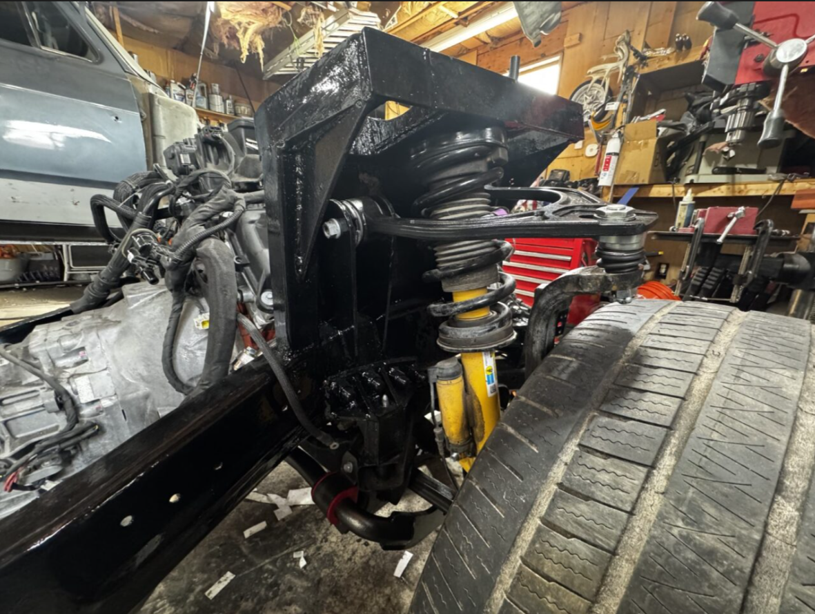
Suspension & Subframe Engineering
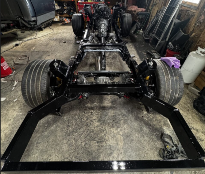
Modern Challenger front and rear subframes were integrated into the D150 frame, requiring custom mounting geometry and structural reinforcement to preserve factory suspension kinematics.
Engineering work included:
Subframe positioning and leveling
Suspension geometry analysis
Weight distribution considerations
Traction and drivability optimization
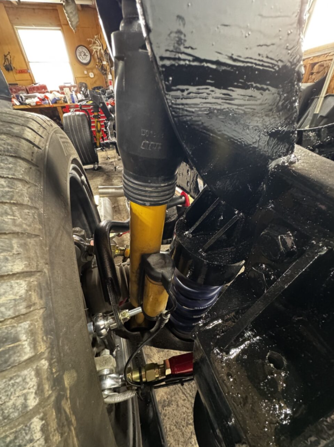
Coil-over and strut mounting structure design
The goal was to retain the handling and stability characteristics of the modern suspension system while adapting it to a fundamentally different chassis architecture.
System Architecture & Constraints
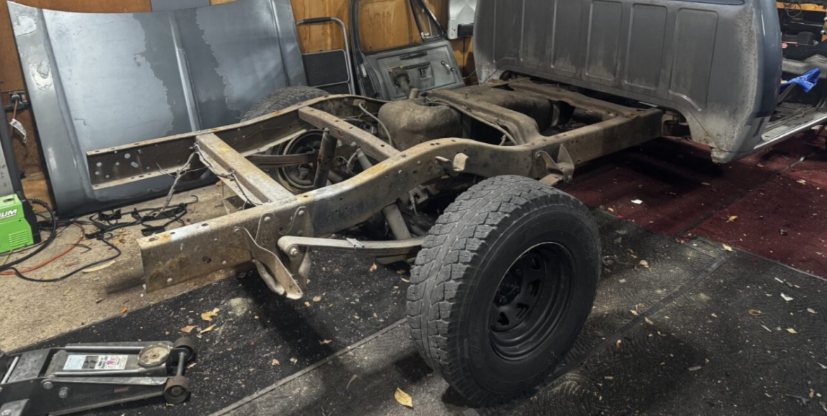
Legacy ladder-frame truck chassis (1984 D150)
Modern donor architecture (2022 Dodge Challenger ScatPack Widebody)
Fixed hard points imposed by frame geometry and cab structure
Packaging constraints for drivetrain, suspension, steering, and HVAC
Structural compatibility between unibody-derived subframes and a body-on-frame platform
This project required reconciling incompatible vehicle architectures while preserving correct suspension kinematics, drivetrain alignment, and structural load paths.
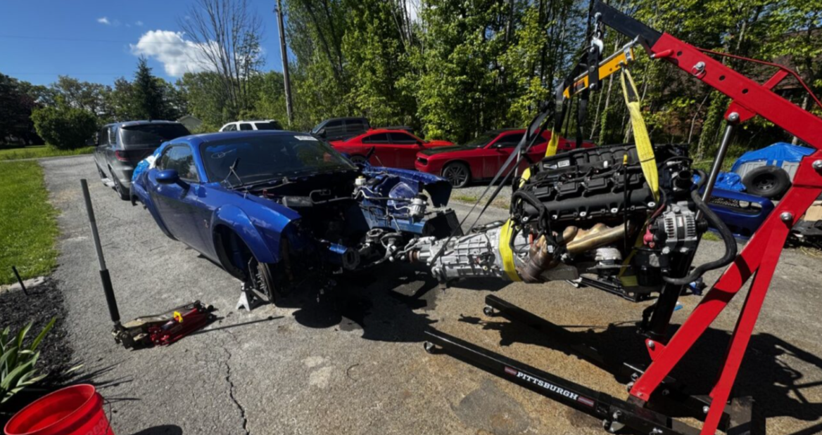
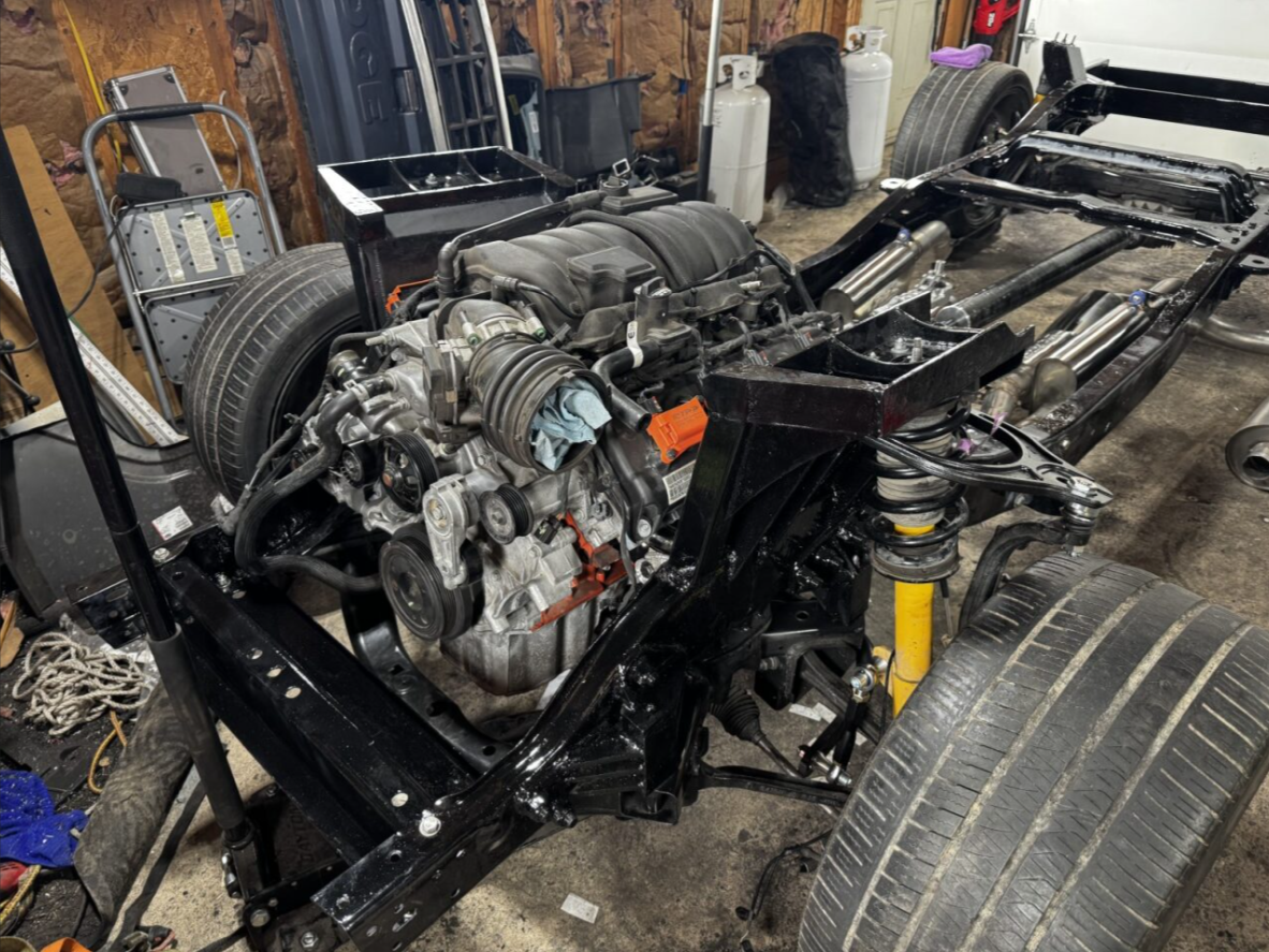
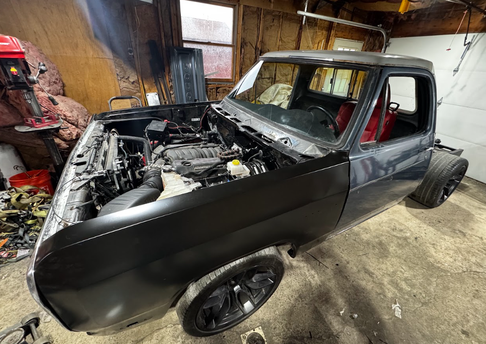
Modern Powertrain Integration
A modern 392 HEMI powertrain was integrated into the D150 chassis with attention to drivetrain alignment, mount geometry, and serviceability. Custom engine and transmission mounting solutions were developed to maintain correct driveline angles while accommodating chassis constraints.
Key considerations included:
Engine and transmission positioning
Driveshaft alignment and angularity
Clearance for exhaust, steering, and suspension travel
Structural load transfer into the frame
Powertrain’s role in the center of gravity height
Use of the Challenger fuel tank to ensure proper fuel supply, including fuel gauge and range accuracy within the OEM electronics
Structural Design & Fabrication
Custom structural components were designed and fabricated to support the modern suspension and drivetrain systems. These components include:
Subframe mounting brackets
Coil-over and strut support structures
Reinforcement elements for load distribution
Frame modifications required for packaging and clearance
Shortening the frame to the short bed length to best match the Challenger wheelbase
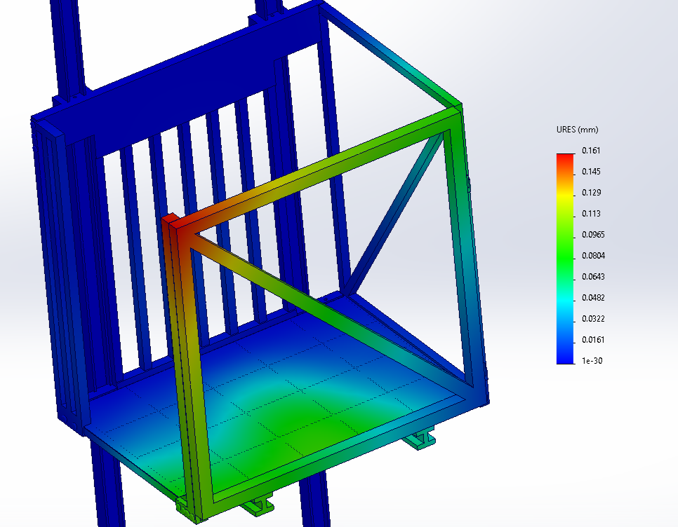
During the Finite Element Analysis, the components were subjected to the worst-case loading to ensure proper operation during extreme use. For the subframe mounting locations, they were subjected to a 1.5G lateral acceleration in both horizontal directions, as well as a 6-inch instantaneous compression of the suspension, resulting in a large upward acceleration under assumed resonance conditions.
All subframe mounting locations were fabricated out of 5/16ths thickness ASTM A572 Grade 50 plate steel to ensure rigidity and proper load transfer to the frame.
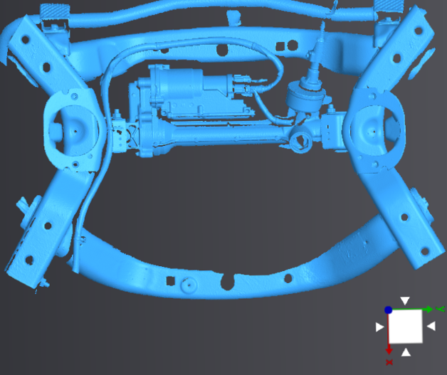
All structural work was developed with dimensions obtained from 3D scanning during my undergraduate research titled “Accuracy Validation of a Consumer-Grade Structured-Light 3D Scanner.”
CAD Design
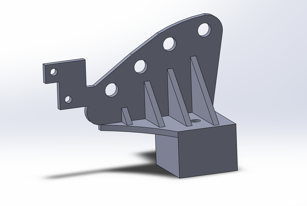
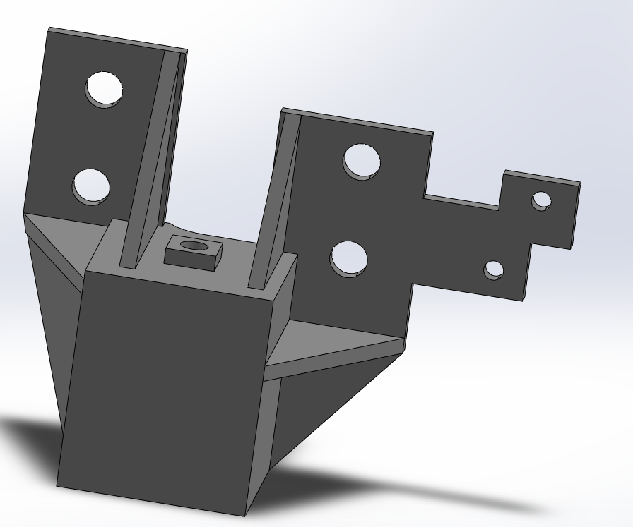
Rear Subframe, Front Mount Design
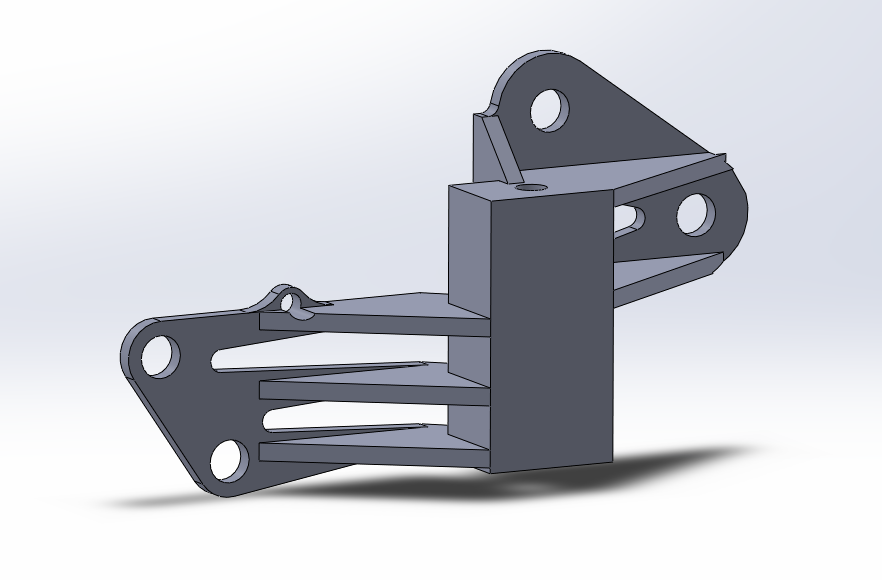
Rear Subframe, Rear Mount Design
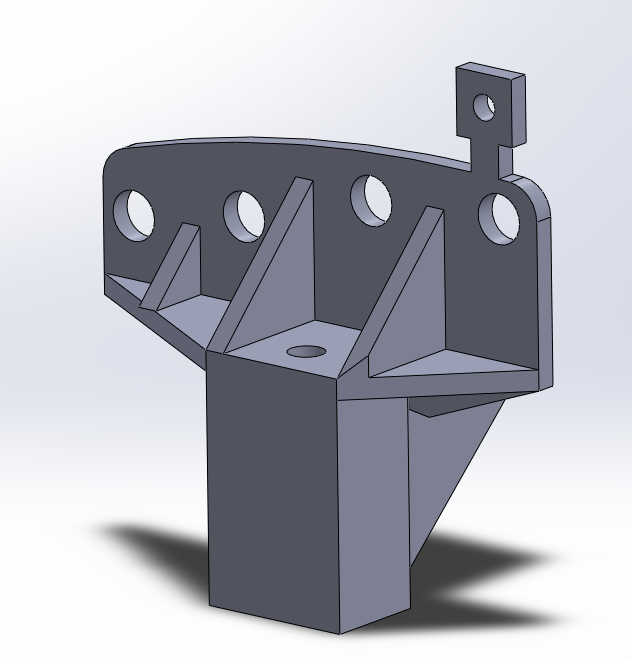
Front Subframe, Front Mount Design
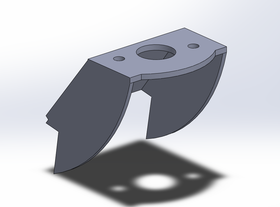
Front Subframe, Rear Mount Design
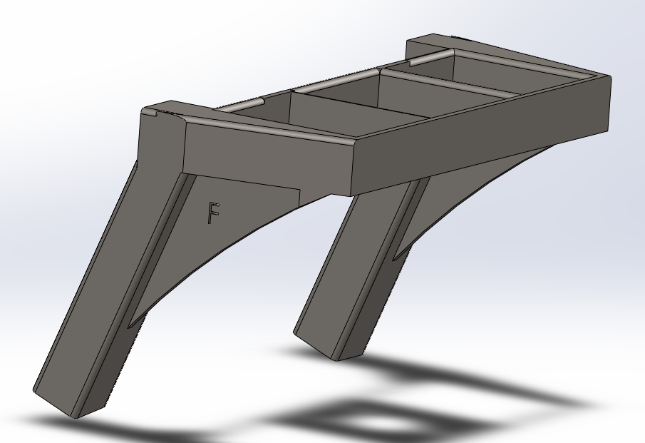
Rear Strut Mount Design
Finite Element Analysis
Front Coilover Mount Design
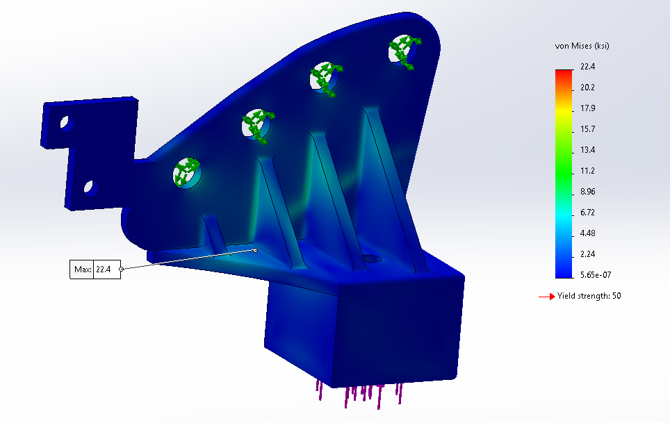
Analysis of stress distribution - worst case loading
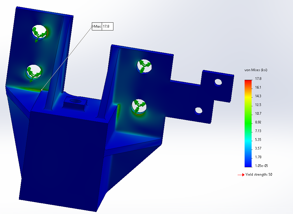
Analysis of stress distribution - worst case loading
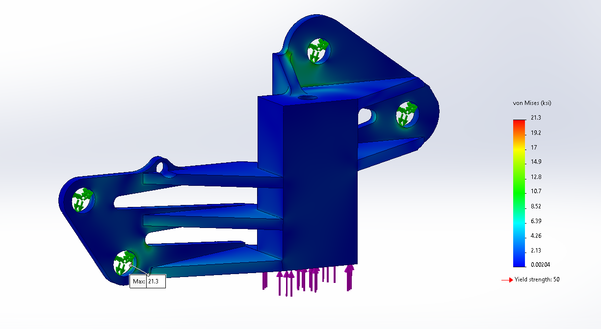
Analysis of stress distribution - worst case loading
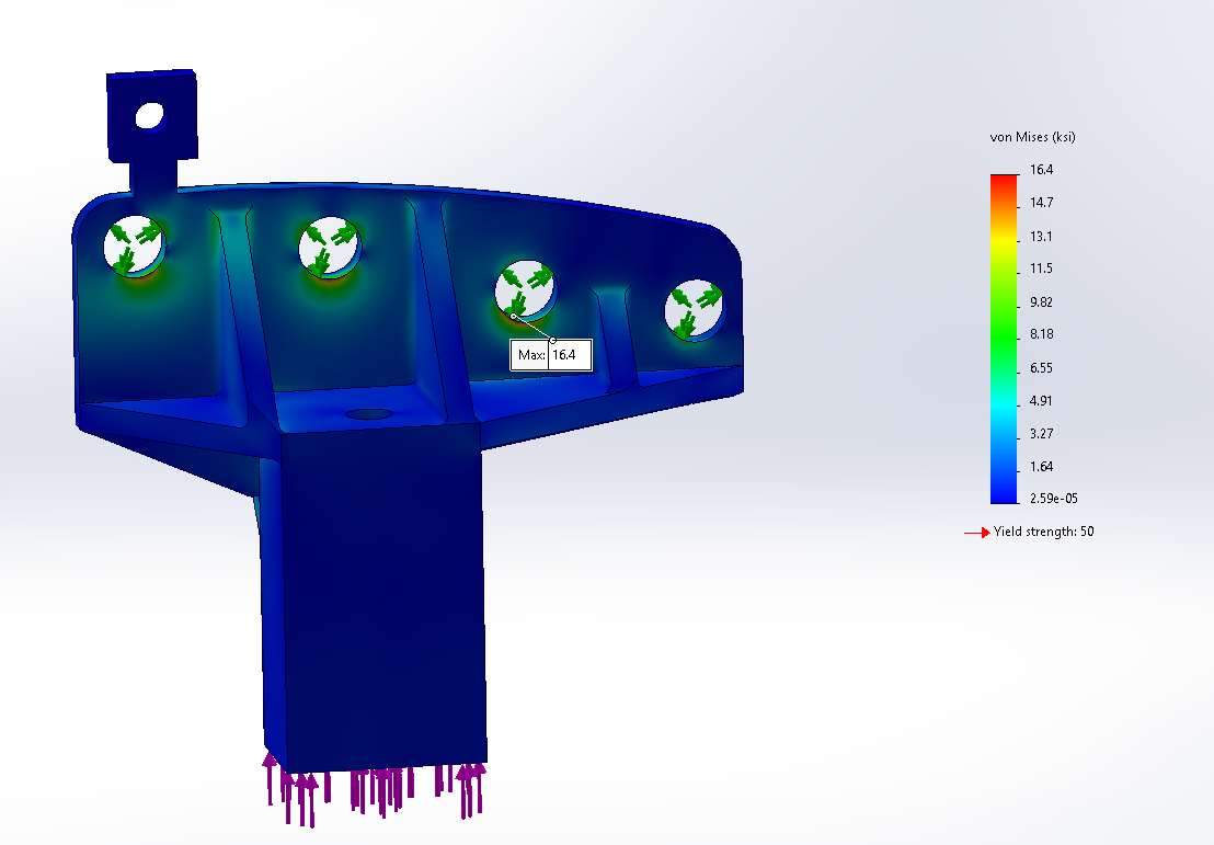
Analysis of stress distribution - worst case loading
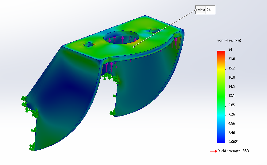
Analysis of stress distribution - worst case loading
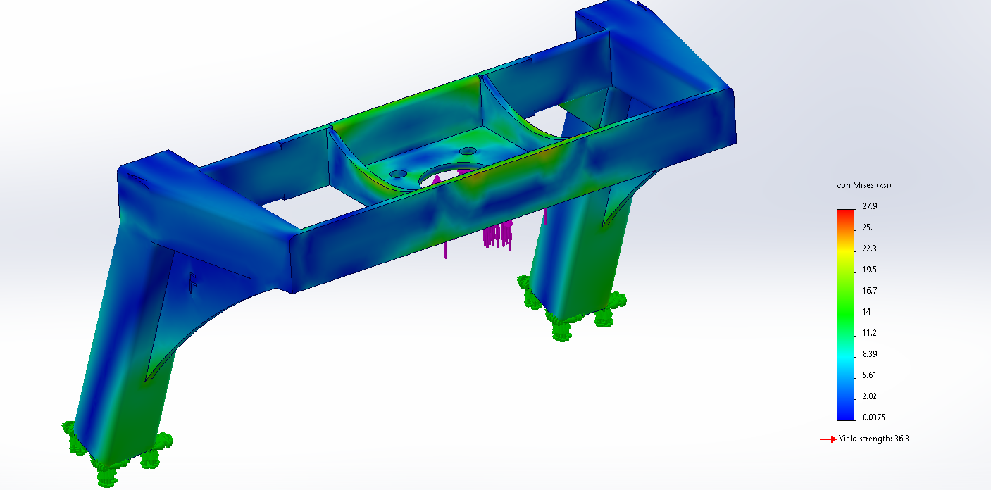
Analysis of stress distribution - worst case loading
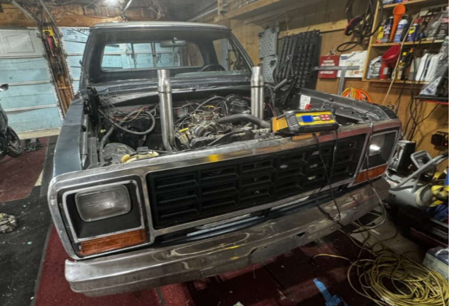
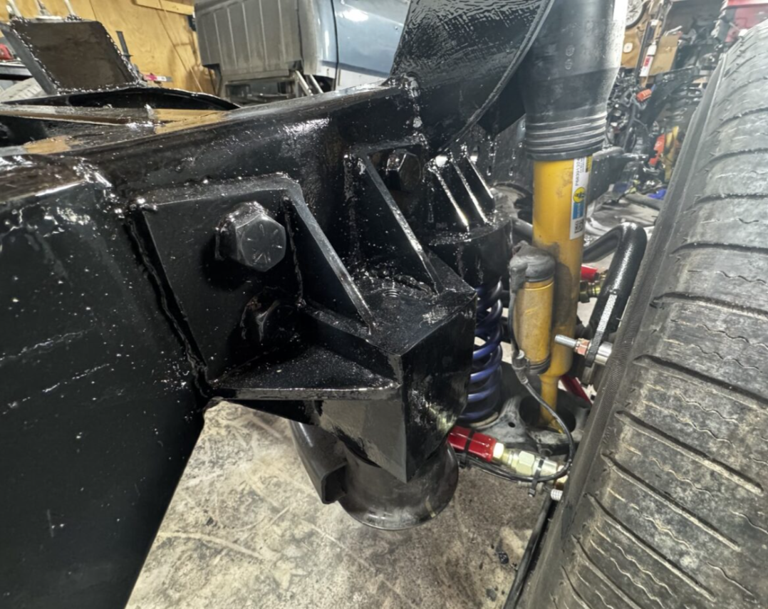
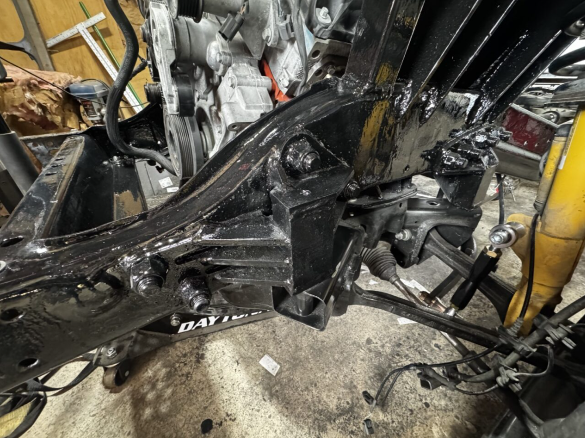
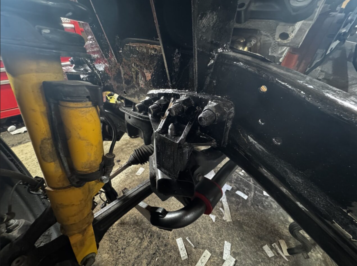
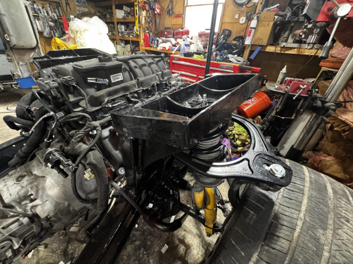
Middle of Fabrication
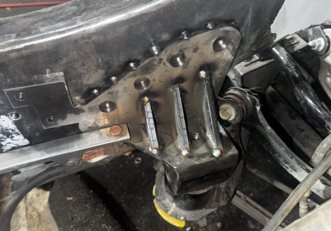
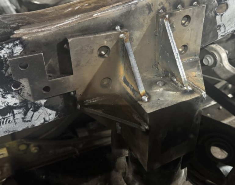
During Fabrication process
During Fabrication process
During Fabrication process
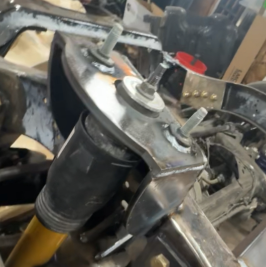
During Fabrication process
During Fabrication process
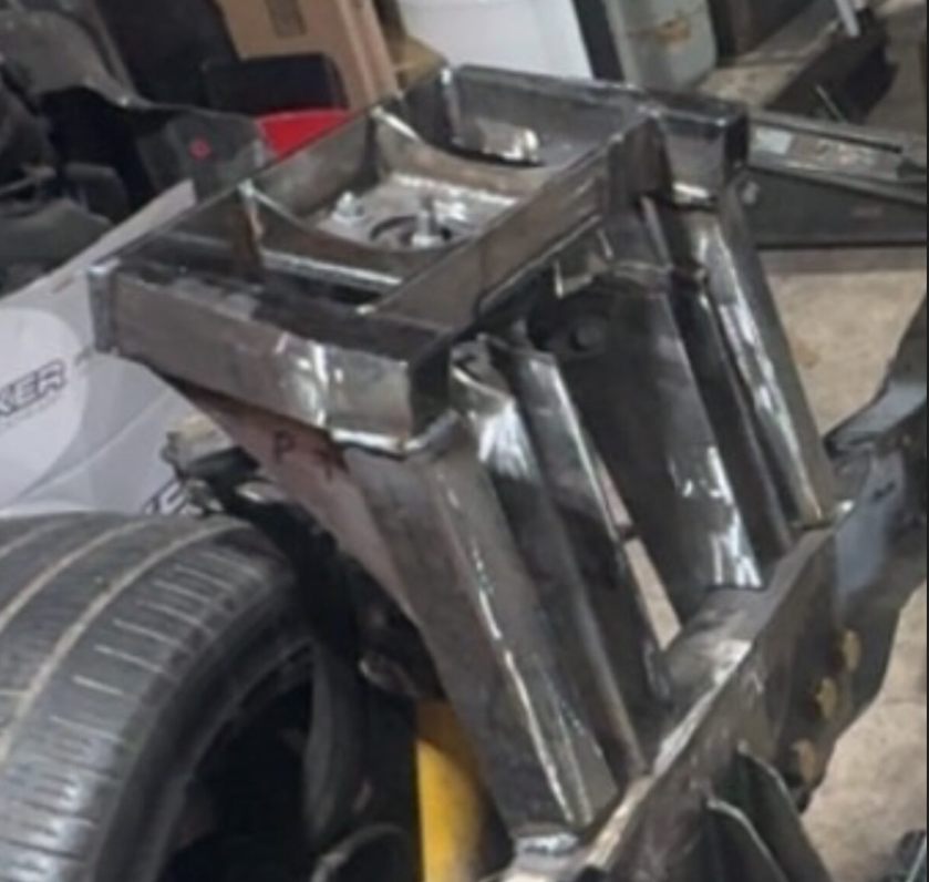
During Fabrication process
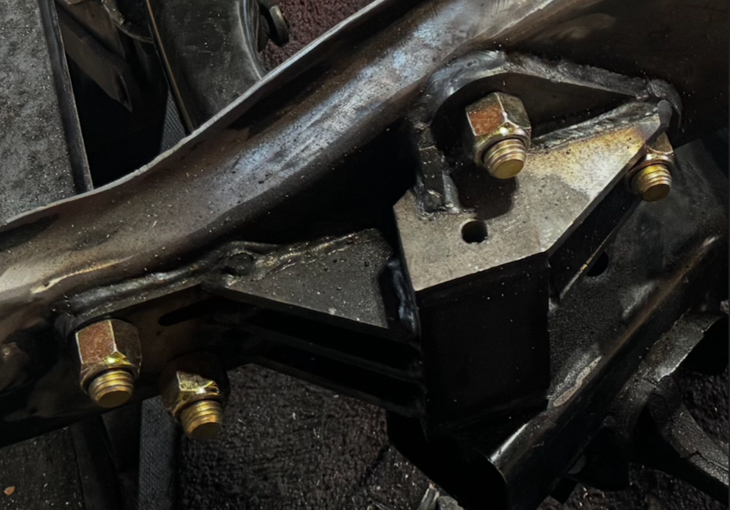
Complete
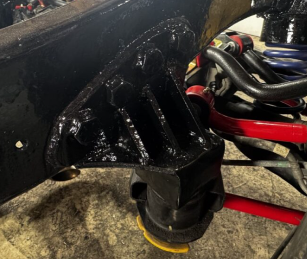
Painted, Final assembly finished
Painted, Final assembly finished
Painted, Final assembly finished

Painted, Final assembly finished
Painted, Final assembly finished
Painted, Final assembly finished
HVAC System Design & Integration
The vehicle HVAC system was modified to integrate modern air conditioning and heating functionality into the legacy D150 platform while maintaining OEM-style serviceability and industry-standard interfaces.
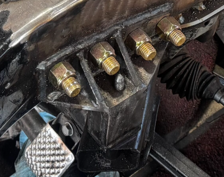
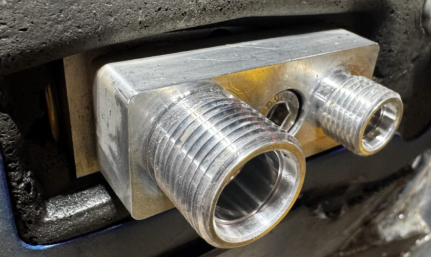
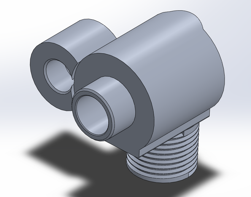
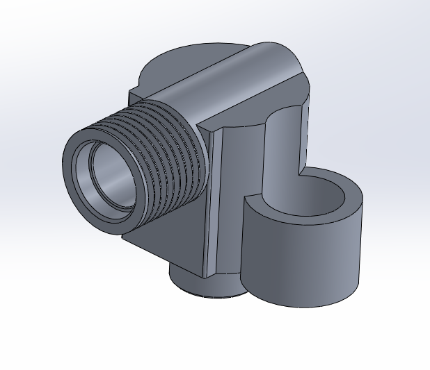
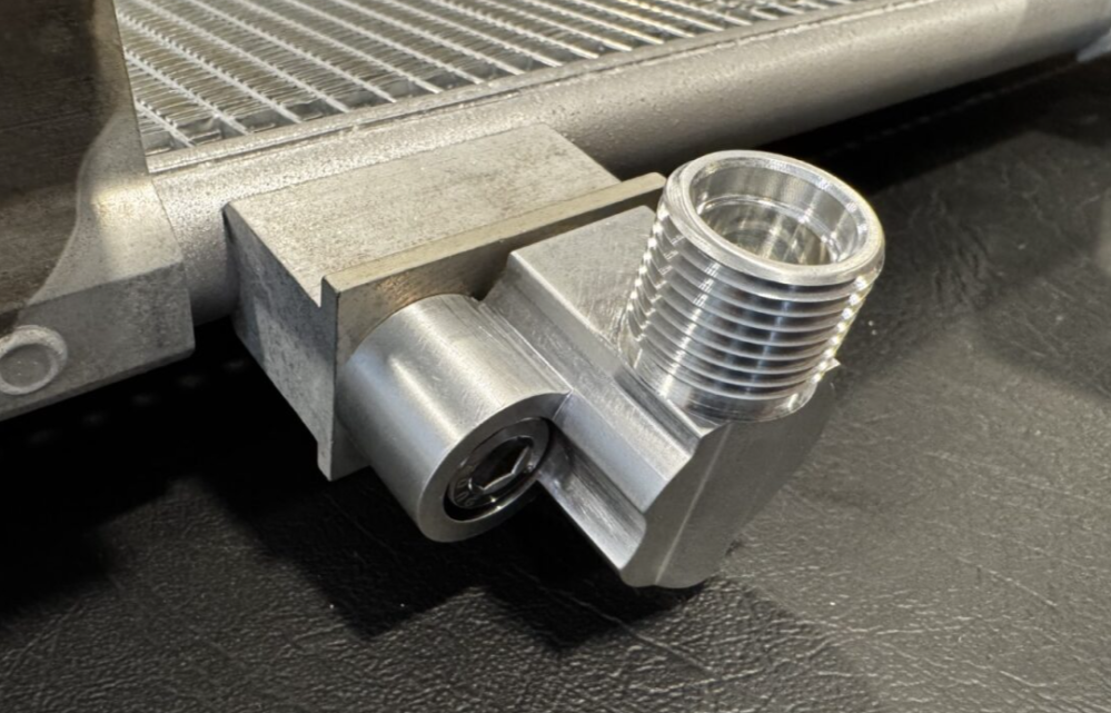
The factory fittings and A/C lines found on the Dodge Challenger were aluminum, non-threaded, O-ring, stud, and nut style fittings. The factory hard lines were not the correct dimensions due to the packaging constraints of the D150, meaning another alternative connection and hose style was required.
Rather than relying on universal or temporary fittings, the system was engineered using industry-standard threaded connections and reduced-barrier hose assemblies to ensure compatibility with modern service equipment, long-term reliability, and compliance with current automotive HVAC practices.
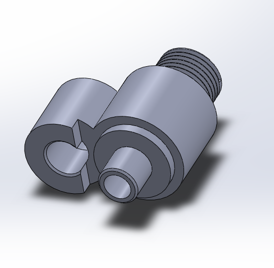
Fitting retention was converted from a stud/nut combination to a single hex cap screw in a recessed hole to avoid blocking the use of the threaded connections.
Key engineering considerations included:
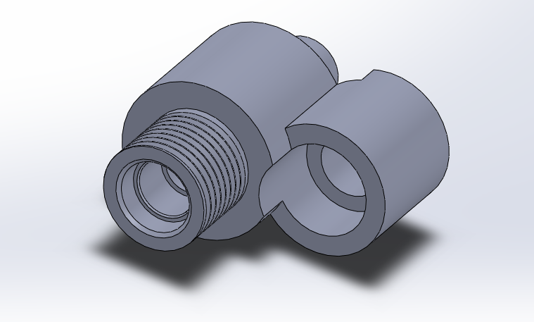
Custom adapter design to interface modern compressors, condensers, and evaporator components with a non-native chassis
Selection and implementation of OEM-style threaded fittings and sealing strategies
Hose routing and packaging under tight engine bay and firewall constraints
Service access and future maintainability
Thermal system integration with existing engine cooling architecture
This approach prioritized repeatable serviceability, leak resistance, and professional-level integration, aligning the HVAC system with modern OEM standards rather than aftermarket conventions.
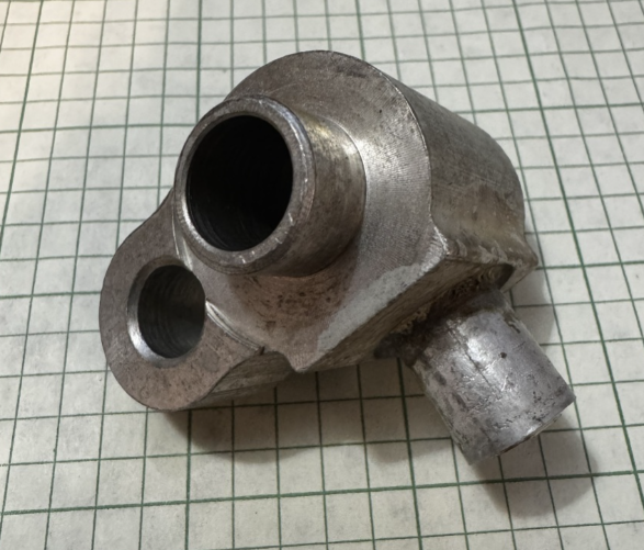
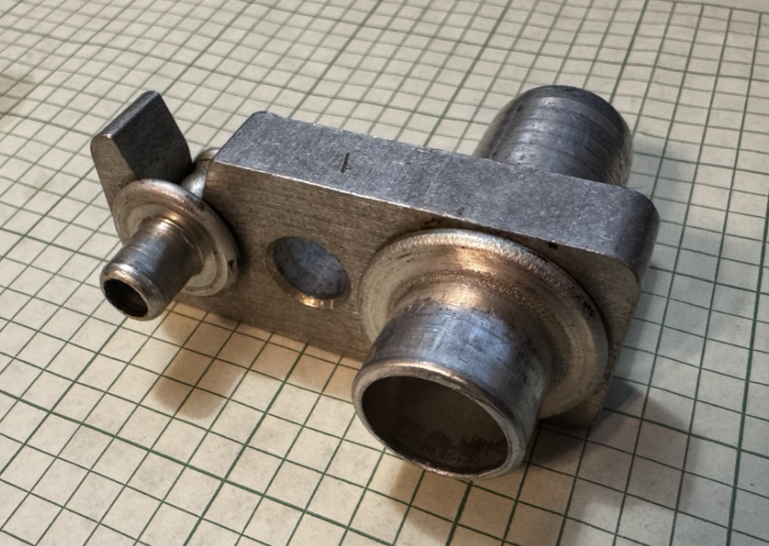
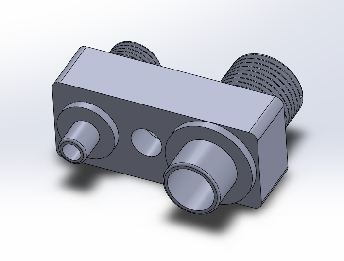
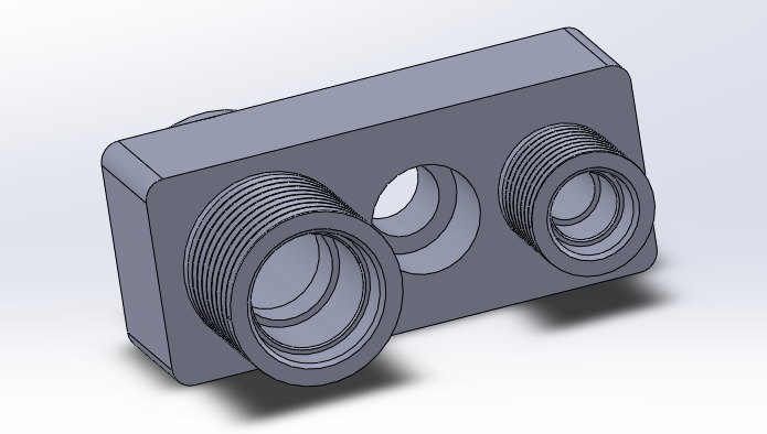
A/C Firewall connection (Liquid + Discharge)
Liquid line
Converted from Mopar Proprietary to IMACA #6 standard threaded connection
Discharge line
Converted from Mopar Proprietary to IMACA #10 standard threaded connection
Condenser - Small port (High side liquid line)
Converted from Mopar Proprietary to IMACA #6 Standard Threaded Connection
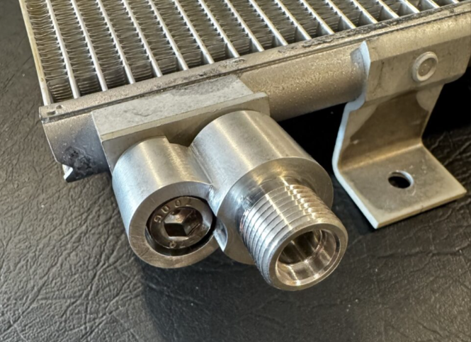
Condenser - Large port connection (Low-pressure return)
Converted from Mopar Proprietary to IMACA #8 standard threaded connection
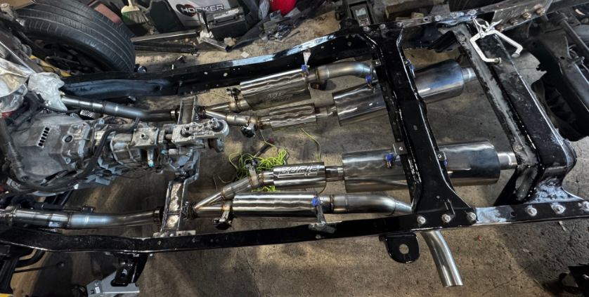
Valvetronic Exhaust System Design
As part of the D150 modernization effort, a dual-mode valvetronic exhaust system was designed to balance daily drivability with performance-oriented sound and flow characteristics. The goal was to retain OEM-level comfort during normal operation while enabling a high-flow, aggressive exhaust path on demand.
The system utilizes electronically actuated exhaust valves to switch between two parallel exhaust paths:
Quiet Mode:
A full-length, OEM-style exhaust configuration designed to minimize cabin noise and drone while maintaining acceptable backpressure for street use.Performance Mode:
A straight-through, low-restriction exhaust path utilizing a high-performance muffler to maximize exhaust flow and acoustic output.
Electrical & Electronic Systems Integration
Modern vehicle electronics are in the process of being integrated into the legacy platform, including:
Challenger wiring harness architecture
Electronic power steering
Adaptive damping systems
ABS-equipped braking system
OEM-style controls and diagnostics
OEM Fuel system and Electronic fuel pump w/ sensors
This requires careful planning of routing, mounting, grounding, and system interoperability to ensure reliable operation across all subsystems.

Engine Modifications
I have personally installed the following modifications to the 392 Hemi:
Comp Cams Stage 2 HRT Camshaft kit
This included new pushrods, lifters, valve springs, valve seals, valve retainers, and Cam Phase limiter.
Cometic MLS Head Gaskets
ARP Head Studs
Laser Iridium Spark Plugs
Ripp High Performance Coil Packs
Engineering Skills Demonstrated
Systems-level mechanical integration
Suspension geometry and vehicle dynamics
Structural design and fabrication
Packaging and constraint-driven design
Electrical system integration
Long-horizon project planning and execution
Validation through real-world assembly and testing
Fabrication & Manufacturing Skills Applied
Welding
MIG welding of structural steel components
Multi-pass welds for load-bearing brackets and crossmembers
Weld joint preparation and post-weld inspection
Cutting & Material Removal
Abrasive cutting and cutoff wheel operations
Precision trimming for packaging and clearance requirements
Controlled removal of legacy frame material
Grinding & Surface Preparation
Weld bead shaping and stress-relief grinding
Surface conditioning for fit-up and coating adhesion
Edge finishing for safety and durability
Drilling & Threading (Tapping)
Precision drilling for structural and mounting features
Manual tapping of threaded holes for brackets and adapters
Thread alignment, depth control, and fastener engagement verification
Fit-Up, Fixturing, and Assembly
Component alignment prior to welding and final fastening
Iterative test-fitting to validate geometry and clearances
Assembly sequencing to preserve suspension and driveline alignment
Surface Treatment & Finishing
Cleaning and preparation for corrosion protection
Priming and painting of fabricated structural components
Final surface treatment following welding and fabrication
Fluid Line Routing & Integration
Fabrication and routing of brake, fuel, and A/C lines
Line routing to avoid heat, abrasion, and suspension interference
Integration of industry-standard fittings and serviceable connections
Current Status
The vehicle is currently undergoing bodywork and rust repair. The truck runs and drives as intended with no check engine light and all systems operational. The tuning is being done remotely by OST Dyno, who verified it is ready for a longer drive once it is street legal. I am actively working on the bed of the truck, which will have a wood floor with channels to accommodate the main body harness and protect it from the elements, and keep it out of view. The wood floor will also allow me to create Service panels that can be opened in the bed floor (hidden under the wood) to allow access to the fuel tank, rear strut towers, and EVAP system without removing the bed.
Recently, I have successfully integrated the electronic door latches with new doors (not pictured yet), which will be controllable with the key fob as OEM on the Challenger. I drove it for approximately 2 miles at various speeds on 06/12/2026 and verified the functions of these systems: Electronic Power steering, ABS Braking system, Engine cooling system, Heat management (heat shielding around high-temperature areas at operating temperature), Power transmission (All 6 gears and Reverse fully functional), and fuel management. All systems operated as intended, and no unintended trouble codes or lights appeared on the dashboard.
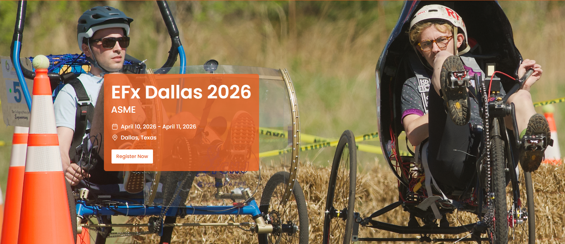
ASME Human-Powered Vehicle Challenge — ASME EFx of Dallas 2026 (In progress)

Project Overview
The ASME Human-Powered Vehicle Challenge (eHPVC) is a national engineering competition focused on the design, analysis, and fabrication of a safe, efficient, and high-performance human-powered vehicle within a strict regulatory framework.
This project involves translating performance goals and competition rules into a fully realized vehicle design, balancing efficiency, safety, manufacturability, and reliability under aggressive time and budget constraints.
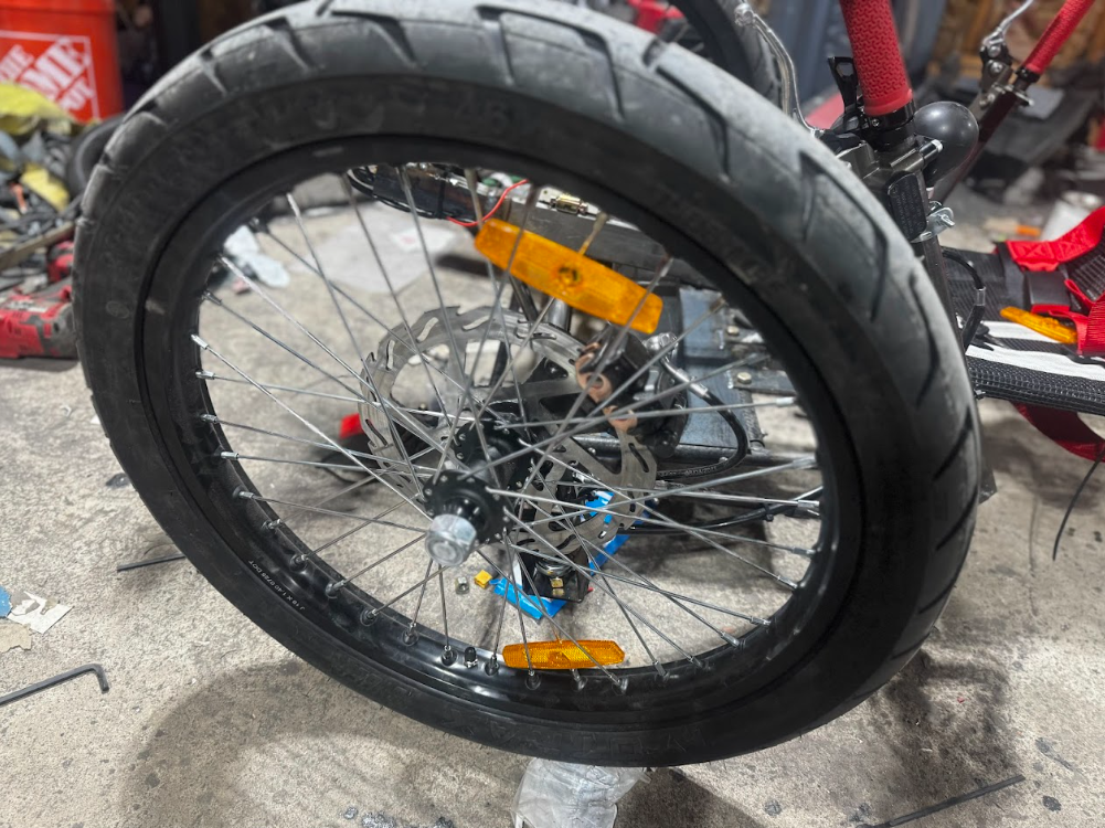
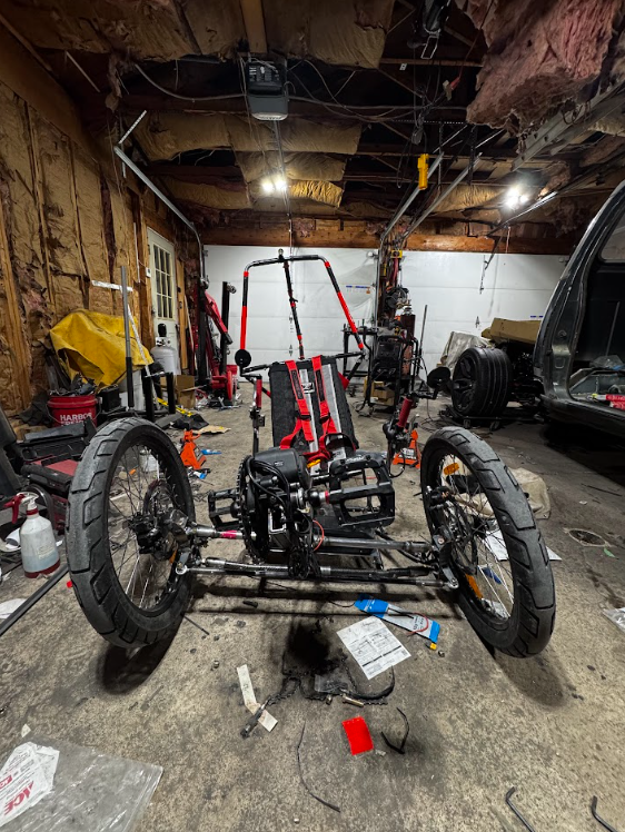
The target of our team’s design, “Carbon Overdraft”, is to utilize modern materials to maximize efficiency and capability by drastically reducing weight and applying tilt while turning principles to allow a better turning radius and faster speed capabilities through turns.
This Project is Sponsored by OSH Cut in Spanish Fork, Utah.
Competition Constraints & Design Requirements
Design decisions are governed by:
ASME eHPVC rules and safety requirements
Rider ergonomics and power delivery
Weight and structural efficiency
Manufacturing capabilities and budget limits
Timeline-driven iteration and testing
All design choices were validated against competition rules to ensure compliance while maximizing performance within allowable limits.
This environment closely mirrors real-world engineering programs where external requirements dictate design boundaries.
Mechanical Design & Analysis
Mechanical systems are being designed using analytical methods and iterative evaluation to balance strength, stiffness, and efficiency.
Engineering work included:
Structural layout and load path definition
Material selection and trade-off analysis
Component sizing based on expected loading
Integration of drivetrain and rider interfaces
Consideration of manufacturability and assembly sequence
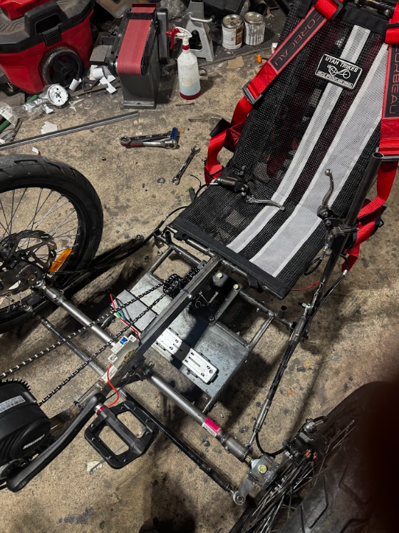
Construction Materials
This design is comprised of two primary materials
Carbon Fiber
Used primarily in tube form, drastically reducing the vehicle’s weight without sacrificing strength.
Steel
Used primarily in load-critical areas like tubing joints, wheel knuckles, tilting mechanism ears, and pins
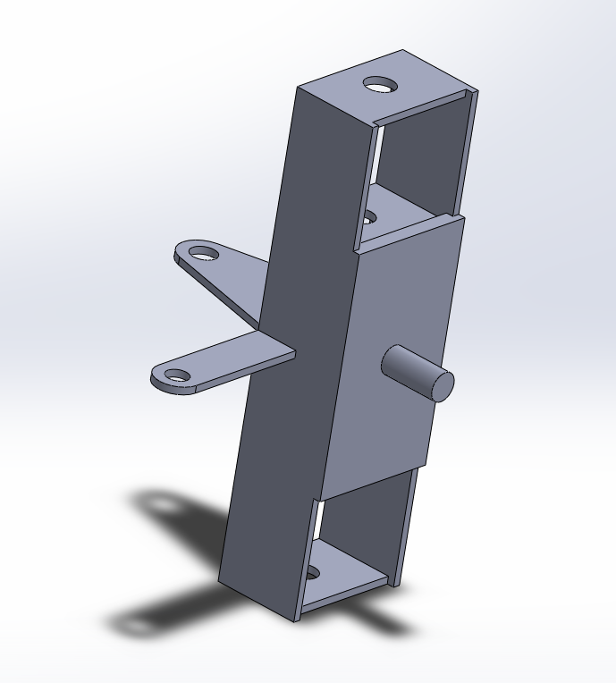
CAD design 1: Preliminary Wheel Knuckle
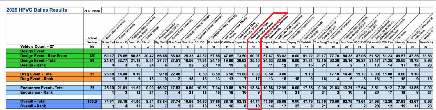
Competition Results
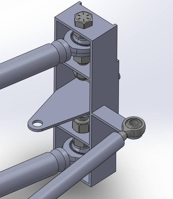
CAD Assembly ref 1: Dual ball joint connections for an additional degree of freedom

CAD Assembly ref 2: complete design
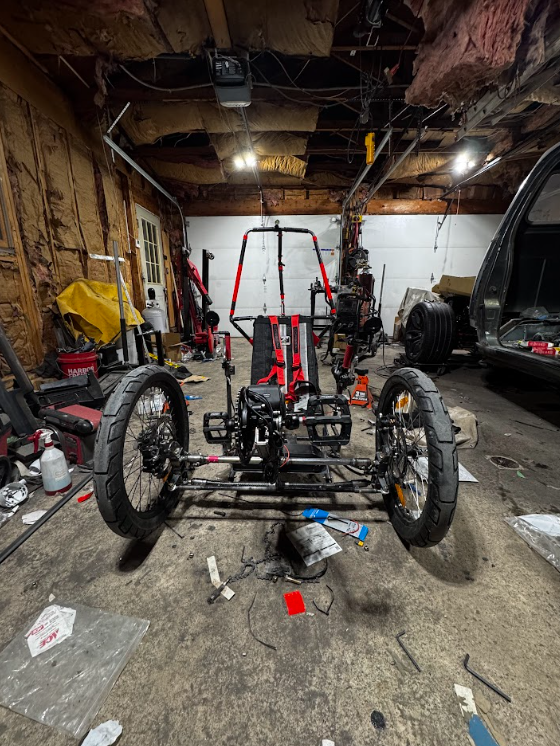
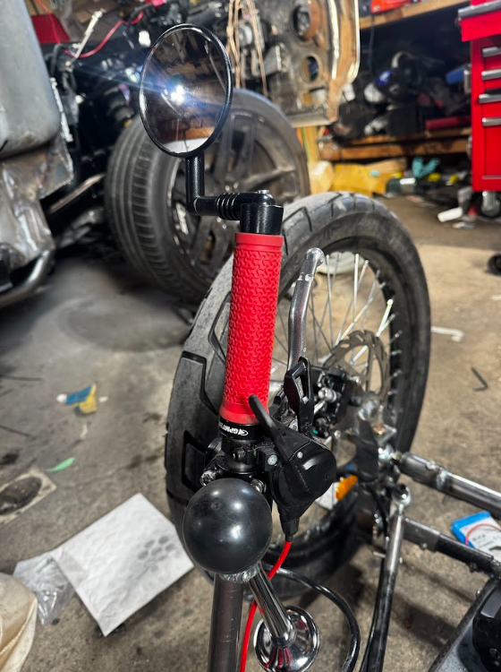

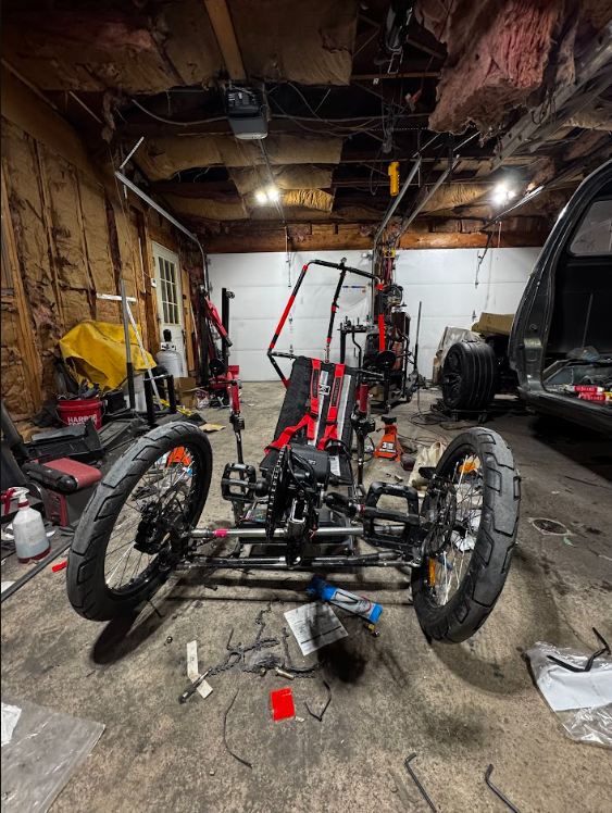
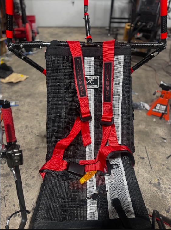
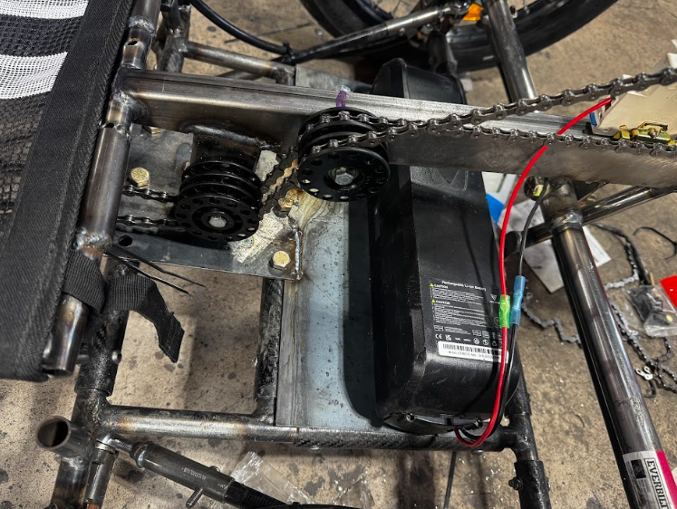
Fabrication & Assembly
The vehicle was fabricated using in-house processes, requiring close coordination between design intent and manufacturing reality.
Key aspects included:
Translating CAD designs into manufacturable components
Managing tolerances and alignment during assembly
Iterative refinement based on fit-up and testing feedback
Ensuring all safety-critical features met inspection standards
This phase reinforces the importance of designing components that could be reliably built within real constraints.
Testing, Validation & Competition Performance
Testing and inspection were used to validate both performance and compliance prior to competition.
This includes:
Functional testing of mechanical systems
Safety inspections and rule compliance checks
Performance evaluation during competition events
Iteration based on observed behavior and feedback
Competition performance provided direct, real-world validation of design assumptions.
Results Continued
Design
In the design category, we scored 8th out of 27, with the judges commenting on the originality of our design.
Drag
In the drag event, we placed 17th out of 27 due to a component failure during our first run of the day. We resolved the issue before the endurance race the following day.
Endurance
In the Endurance race, we placed 9th out of 27, with 37 laps completed for approximately 37 kilometers driven in 2.5 hours.
Overall
Overall, we placed 10th out of 27 for the combination of all events.
Engineering Skills Required
Rule-driven mechanical design
Trade-off analysis under constraints
Team-based engineering coordination
Design-for-manufacturing principles
Validation through testing and competition
Technical communication and documentation
Key Engineering Takeaways
This project reinforces the importance of balancing theoretical design goals with regulatory requirements, manufacturability, and schedule constraints—an experience closely aligned with professional engineering practice.
Extra Notes
This competition marks the first-ever international ASME competition that Penn State Scranton has ever competed in, with a freshly formed ASME chapter that will continue to develop and refine this design in future competitions.
Elevator For Residential Applications
Design Constraints & Safety Considerations
The elevator/lift system was designed under the following constraints (as defined in the project requirements):
Accessibility: Must be wheelchair accessible and suitable for daily use by elderly occupants
Load Capacity: Must withstand a minimum rated load of 500 lb (passenger + mobility device + caretaker)
Safety Priority: Optimize for ease of use and safety as the primary design driver
Space + Cost: Optimize space usage and cost within a residential footprint
Compliance: Must conform to HOA requirements, the Pennsylvania Uniform Construction Code, and applicable ASME codes/standards
Engineering safety considerations guiding the mechanical design included:
Defined passenger/payload load cases and conservative assumptions
Static and dynamic loading conditions (start/stop, braking, and transient effects where applicable)
Safety factors appropriate for human-occupancy lifting systems
Fail-safe behavior and mechanical safeguards where feasible
Reliability under repeated operating cycles (durability, wear, and fatigue awareness)
All design decisions were evaluated through the lens of risk mitigation, prioritizing predictable behavior and safe operation over minimizing weight or cost.
Project Overview
This project involved the mechanical engineering design and analysis of a residential elevator/lift system intended to improve accessibility in a two-story home environment. The primary goal was to create a system that is safe, reliable, space-efficient, and compliant with applicable codes, while meeting defined load and accessibility requirements.
The work focused on translating real-world functional needs into an engineered mechanical system, emphasizing failure prevention, predictable behavior, and long-term operability over aggressive optimization.
Mechanical Design & Analysis
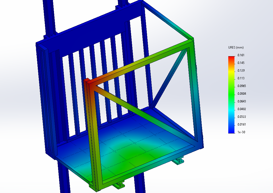
The mechanical system was designed to support anticipated loads while maintaining structural integrity and alignment throughout the operating range.
Engineering work included:
Load path identification and force distribution
Component sizing based on expected stresses
Consideration of wear, fatigue, and long-term operation
Mechanical interface definition between subsystems
Evaluation of potential failure modes and mitigations
Analytical methods were used to ensure all primary components operated within acceptable limits under worst-case loading scenarios.
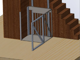
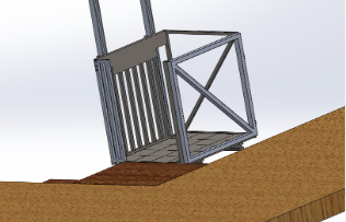
CAD Design: lowered/door open position
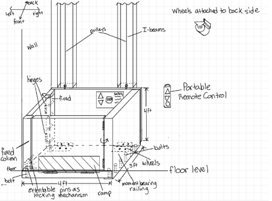
Design Drawing (1): Elevator Layout
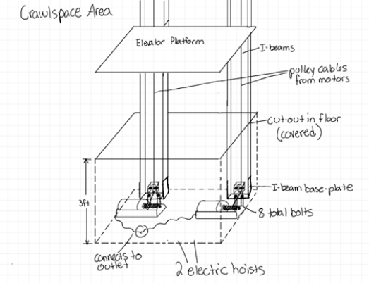
Design Drawing (2): Electric lift system
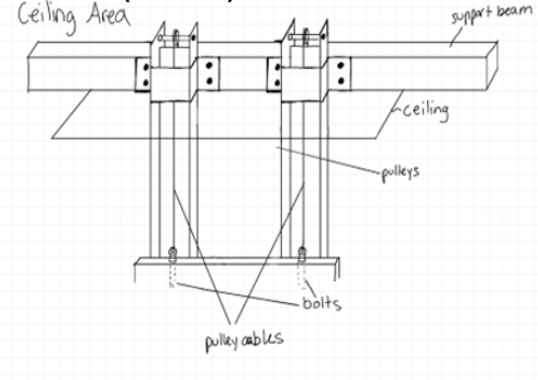
Design Drawing (5): Upper Structure Support Method
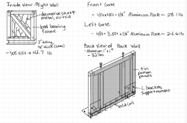
Design Drawing (4): Decoration and safety panels
Safety-Critical Design Philosophy
Unlike performance-driven projects, this design prioritized:
Conservative assumptions
Redundant load paths where appropriate
Predictable mechanical behavior
Clear inspection and maintenance considerations
Design decisions favored robustness and clarity over sacrificing a large safety factor for better efficiency, reflecting professional best practices for systems involving human safety.
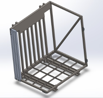
CAD Design: Rigid Steel Frame
CAD Design: raised position
Awards & Recognition:
1st Place – Penn State Scranton Undergraduate Research Fair (spring 2025)
1st Place – Eastern Regional Research Symposium (Penn State Brandywine, spring 2025)
CAD Design: Finite Element Analysis
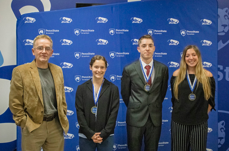
Undergraduate Research Fair, Penn State Scranton (Spring 2025)
Eastern Regional Research Symposium, Penn State Brandywine (Spring 2025)
Engineering Skills Demonstrated
Safety-critical mechanical design
Load and stress analysis
Constraint-driven decision making
Conservative engineering judgment
Failure mode awareness
Clear technical reasoning and documentation
Key Engineering Takeaways
This project reinforced the importance of disciplined engineering judgment when designing systems where reliability and safety are non-negotiable. It emphasized that good engineering is often defined not by maximum performance, but by predictable, repeatable, and safe operation under all expected conditions.
Undergraduate Design Poster